Air Micrometers
Variation
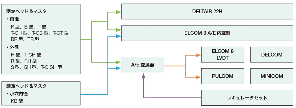
List of Measuring Methods
| Diameter/Roundness | |||
|
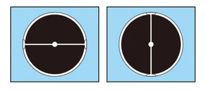
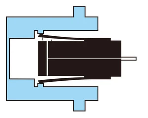
Inner Diameter 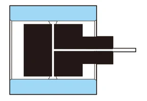 |
 |
 |
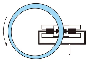
Outer Diameter
 |
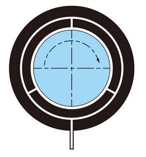
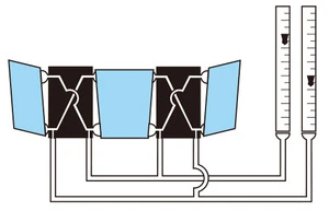
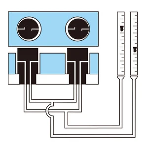
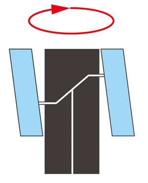
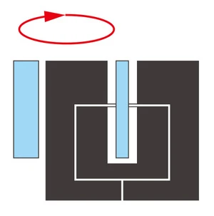
| The inner diameter is measured by inserting the plug type measuring head with air nozzles on both sides into the workpiece, and the taper is measured by moving the head in the axial direction. | Roundness (cylindricity) can be measured by rotating the measuring head one revolution. | Contact type indirect air blow head (leaf type) is used when the measuring surface is confined or rough. | Inner diameter can be measured by inserting a plug type measuring head with air blow nozzles on both sides. Taper can be measured by moving the head in the axial direction. |
| Average Diameter/Triangle | Depth | ||
Inner Diameter
 |
Outer Diameter
 |
 |
 |
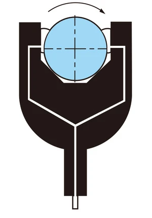
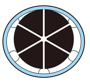
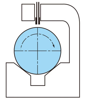
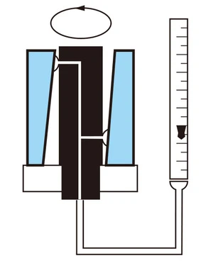
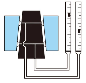
| The average inner diameter can be measured by placing three or more jets at equiangular locations. Roundness can be measured by rotating the workpiece with three nozzles. | 3 The average outer diameter can be measured by placing three or more nozzles at equiangular locations. Roundness deformation can be measured by rotating the workpiece. | Roundness can be measured by mounting a nozzle on a stand and rotating the workpiece on a V stand or a measuring stand. | Use a dedicated measuring instrument with a precision head. Depth is measured by simply inserting the workpiece. |
| Flatness | Concentricity / Eccentricity | ||
 |
 |
||
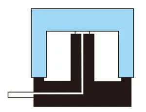
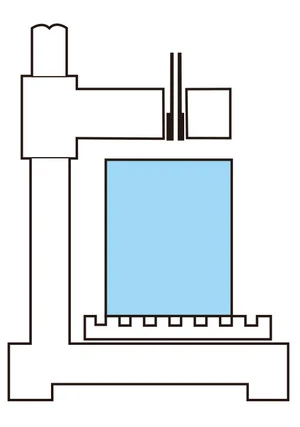
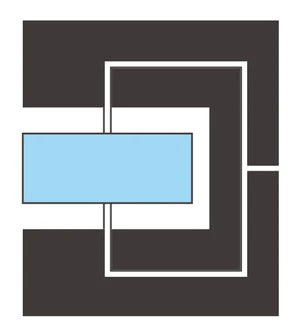
| Move a workpiece to the right and left on a nozzle built-in measuring stand, or use a dedicated measuring unit with several built-in nozzles to measure flatness. | Concentricity can be measured by measuring the wall thickness. |
| Squareness | Parallelism | ||
Inner Diameter
 |
Outer Diameter
 |
Angled Items
 |
 |
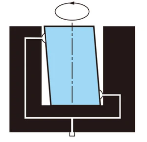
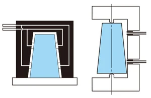
| Squareness can be measured by rotating a dedicated measuring head with a stepped nozzle as shown above 180°. | Squareness is measured by providing a nozzle on one side of the workpiece. | Parallelism can be measured by using a similar procedure as that use to measure squareness. | |
| Taper | Height | Thickness | |
Inner Diameter
 |
Outer Diameter
 |
 |
 |
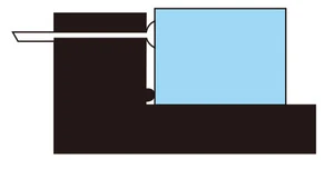
| Taper can be measured from the difference in float position by simply inserting the workpiece. | Measurement can be performed from a nozzle mounted on a stand. | Using a measuring head with air blow in both sides eliminates error due to dust or a warp. | |
| Distance Between Centers | Multi-Point Simultaneous Measurement | ||
 |
 |
||
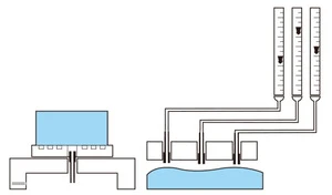
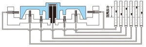
| Distance between centers is measured from the difference in movement of each float by simply inserting the workpiece. A dedicated measuring instrument is used. | The dimensions at multiple points can be simultaneously measured by using a dedicated measuring instrument. This enables one-glance judgment of whether or not the workpiece is within tolerances by simply placing it in the device. |
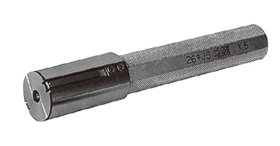
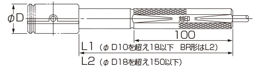
Direct-blow Type (Non-contact) Inner Diameter Measuring Heads
The most commonly used type of non-contact inner diameter measuring head.
Multiple types are available with different nozzle positions to suit the measurement shape and position.
* Ensure that the measurement surface roughness of the measured object is less than Ra1.6.
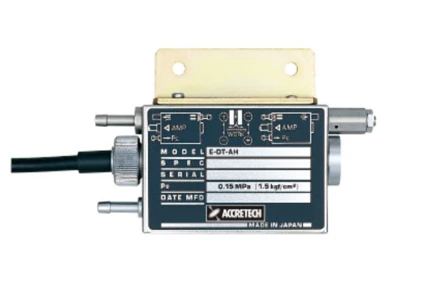
Configurations A/E Converter Deltair
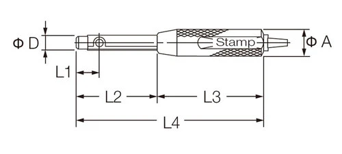
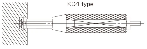
K Type (for small holes)
Suitable for measuring small holes of Φ 4 to Φ 7 diameter.
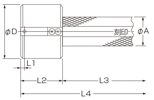
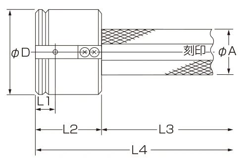
| K Type (for small holes) | ||||||
| Model | Nominal Dimension Φ D | L1 | L2 | L3 | L4 | Φ A |
| K04 type | Φ 4 ≤ Φ D ≤ Φ 7 | 4 | 29 | 50 | 79 | 12 |
| K10 type | Φ 4 ≤ Φ D ≤ Φ 7 | 10 | 35 | 50 | 85 | 12 |
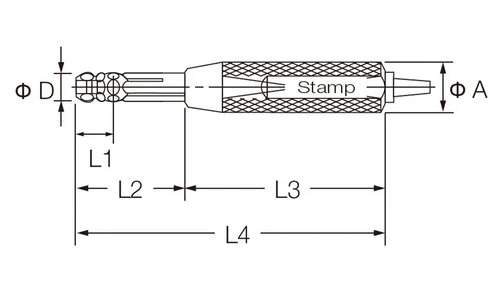
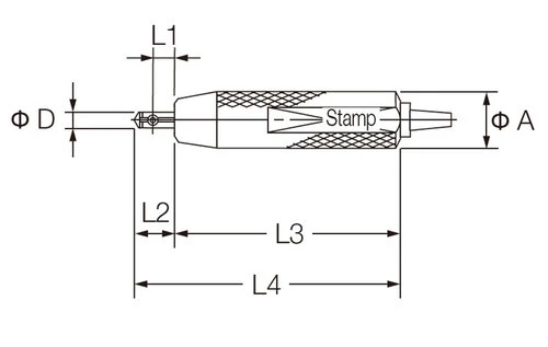
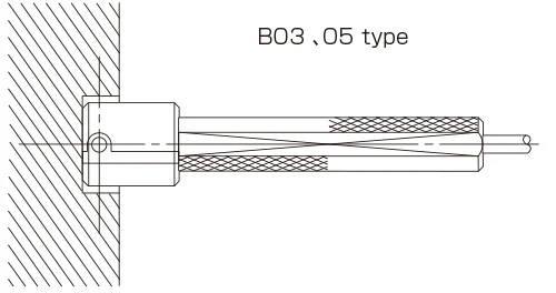
B Type
The nozzle hole is located 3 or 5 mm from the head tip, allowing measurement of shallow holes or the far end of holes.
| B Type | ||||||
| Model | Nominal Dimension Φ D | L1 | L2 | L3 | L4 | φ A |
| B03 type B05 type |
Φ 7 ≤ Φ D ≤ Φ 10 | B03=3 B05=5 |
B03=23 B05=25 |
120 | B03=143 B05=145 |
12 |
| Φ 10 < Φ D ≤ Φ 18 | B03=3 B05=5 |
25 | 120 | 145 | 12 | |
| Φ 18 < Φ D ≤ Φ 40 | B03=3 B05=5 |
30 | 100 | 130 | 18 | |
| Φ 40 < Φ D ≤ Φ 70 | B03=3 B05=5 |
30 | 100 | 130 | 25 | |
| Φ 70 < Φ D ≤ Φ 100 | B03=3 B05=5 |
35 | 100 | 135 | 32 | |
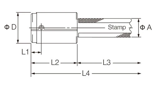
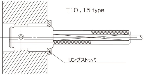
The nozzle hole is located 10 to 30 mm from the head tip, making it suitable mainly for through-hole measurement.
| T Type | ||||||
| Model | Nominal Dimension Φ D | L1 | L2 | L3 | L4 | Φ A |
| T10 type T15 type T20 type T25 type T30 type |
Φ 7 ≤ Φ D ≤ Φ 10 | T10=10 T15=15 T20=20 |
T10=35 T15=35 T20=40 |
120 | T10=155 T15=155 T20=160 |
12 |
| Φ 10 < Φ D ≤ Φ 18 | T10=10 T15=15 T20=20 |
T10=35 T15=35 T20=40 |
120 | T10=155 T15=155 T20=160 |
12 | |
| Φ 18 < Φ D ≤ Φ 40 | T10=10 T15=15 T25=25 |
T10=35 T15=35 T25=50 |
100 | T10=135 T15=135 T25=150 |
18 | |
| Φ 40 < Φ D ≤ Φ 70 | T10=10 T15=15 T25=25 |
50 | 100 | 150 | 25 | |
| Φ 70 < Φ D ≤ Φ 100 | T10=10 T15=15 T30=30 |
60 | 100 | 160 | 32 | |
Direct-blow Type (Non-contact) Inner Diameter Carbide Measuring Heads

Non-contact inner diameter measuring head with enhanced wear resistance through the use of carbide guide sections or carbide-faced guide sections.
* Ensure that the measurement surface roughness of the measured object is less than Ra1.6.
Configurations A/E Converter Deltair
T-CK Type (for small holes)
Suitable for measuring small holes of Φ 4 to Φ 7 diameter.
| T-CK Type (for small holes) | ||||||
| Model | Nominal Dimension Φ D | L1 | L2 | L3 | L4 | Φ A |
| T-CK05 type | Φ 4 ≤ Φ D ≤ Φ 7 | 5 | 35 | 50 | 85 | 12 |
| T-CK10 type | Φ 4 ≤ Φ D ≤ Φ 7 | 10 | 35 | 50 | 85 | 12 |
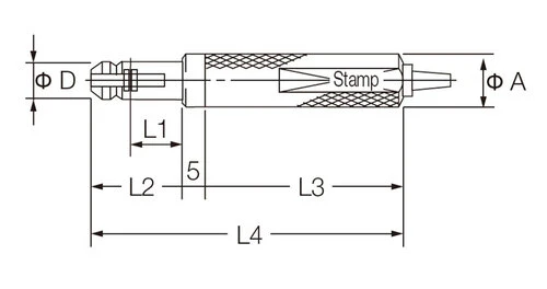
T-CB Type
The nozzle hole is located 5 mm from the head tip, allowing measurement of shallow holes or the far end of holes.
* Carbide-faced guide sections used for diameters exceeding Φ 30.
| T-CB Type | ||||||
| Model | Nominal Dimension Φ D | L1 | L2 | L3 | L4 | Φ A |
| T-CB05 type | Φ 7 ≤ Φ D ≤ Φ 10 | 5 | 45 | 120 | 165 | 12 |
| Φ 10 < Φ D ≤ Φ 18 | 5 | 45 | 120 | 165 | 12 | |
| Φ 18 < Φ D ≤ Φ 30 | 5 | 45 | 100 | 145 | 18 | |
| Φ 30 < Φ D ≤ Φ 70 | 5 | 35 | 100 | 135 | 25 | |
| Φ 70 < Φ D ≤ Φ 90 | 5 | 40 | 100 | 140 | 32 | |
T-CT Type
The nozzle hole is located 10 to 25 mm from the head tip, making it suitable mainly for through-hole measurement.
* Carbide-faced guide sections used for diameters exceeding Φ 30.
| T-CT Type | ||||||
| Model | Nominal Dimension Φ D | L1 | L2 | L3 | L4 | Φ A |
| T-CT10 type T-CT20 type T-CT25 type |
Φ 7 ≤ Φ D ≤ Φ 10 | T-CT10=10 T-CT20=20 |
45 | 120 | 165 | 12 |
| Φ 10 < Φ D ≤ Φ 18 | T-CT10=10 T-CT20=20 |
45 | 120 | 165 | 12 | |
| Φ 18 < Φ D ≤ Φ 30 | T-CT10=10 T-CT20=20 |
45 | 100 | 145 | 18 | |
| Φ 30 < Φ D ≤ Φ 70 | T-CT10=10 T-CT25=25 |
50 | 100 | 150 | 25 | |
| Φ 70 < Φ D ≤ Φ 90 | T-CT10=10 T-CT25=25 |
50 | 100 | 150 | 32 | |
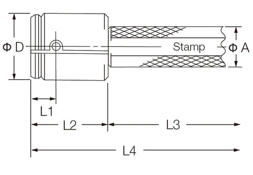
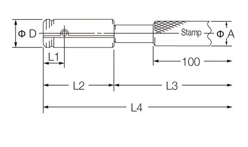
Leaf Type (Contact Indirect-blow) Inner Diameter Measuring Heads
Contact-type inner diameter measuring head that uses leaf contacts.
Mainly used when the surface being measured is rough or the width of the measurement position is narrow.
* Ensure that the measurement surface roughness of the measured object is less than Ra3.2.
* There is the risk of contact scratches depending on the type of material of the workpiece.
Configurations A/E Converter Deltair
BR Type
The nozzle hole is located 2 mm from the contact, allowing measurement of shallow holes or the far end of holes.
| BR Type | ||||||
| Model | Nominal Dimension Φ D | L1 | L2 | L3 | L4 | φ A |
| BR02 type | Φ 10 ≤ Φ D ≤ Φ 14 | 2 | 50 | 120 | 170 | 12 |
| Φ 14 < Φ D ≤ Φ 18 | 2 | 50 | 120 | 170 | 12 | |
| Φ 18 < Φ D ≤ Φ 40 | 2 | 50 | 100 | 150 | 18 | |
| Φ 40 < Φ D ≤ Φ 90 | 2 | 50 | 100 | 150 | 25 | |
| Φ 90 < Φ D ≤ Φ 100 | 2 | 50 | 100 | 150 | 32 | |
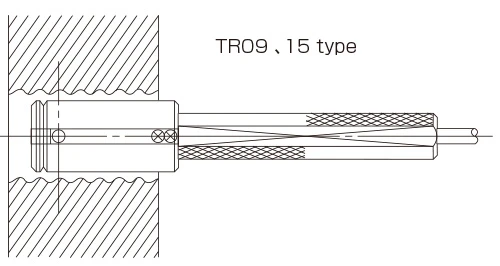
TR Type
The nozzle hole is located 9 or 15 mm from the contact, making it suitable mainly for through-hole measurement.
| TR Type | ||||||
| Model | Nominal Dimension Φ D | L1 | L2 | L3 | L4 | φ A |
| TR09 type TR15 type |
Φ 10 ≤ Φ D ≤ Φ 14 | 9 | 50 | 120 | 170 | 12 |
| Φ 14 < Φ D ≤ Φ 18 | 9 | 50 | 120 | 170 | 12 | |
| Φ 18 < Φ D ≤ Φ 40 | 15 | 50 | 100 | 150 | 18 | |
| Φ 40 < Φ D ≤ Φ 75 | 15 | 50 | 100 | 150 | 25 | |
| Φ 75 < Φ D ≤ Φ 90 | 15 | 60 | 100 | 160 | 25 | |
| Φ 90 < Φ D ≤ Φ 100 | 15 | 60 | 100 | 160 | 32 | |
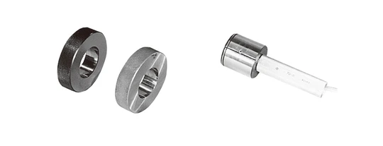
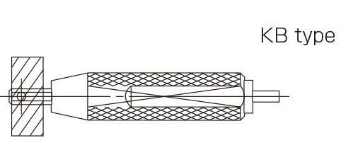
Small Hole Type Inner Diameter Measuring Heads
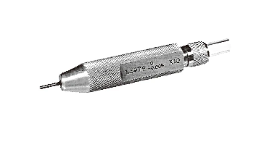
Non-contact inner diameter measuring head with a small-diameter nozzle.
Useful when the object being measured has a small diameter, the width of the measurement point is narrow, or the measurement tolerance is 10 μm or less.
* Ensure that the measurement surface roughness of the measured object is less than Ra0.8.
* Use this measuring head in combination with an AE converter.
Configurations A/E Converter
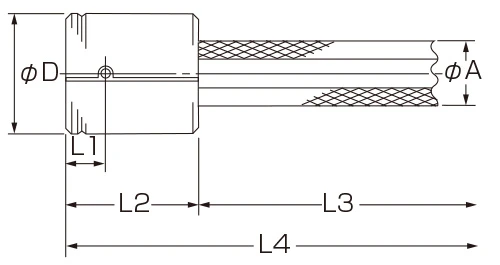
| KB Type | |||||||
| Model | Model | Nominal Dimension Φ D | L1 | L2 | L3 | L4 | Φ A |
| KB type | KB type | Φ 1 ≤ Φ D ≤ Φ 7 | 5 | 9 | 50 | 59 | 12 |
| Φ 4 < Φ D ≤ Φ 10 | 12 | 20 | 50 | 75 | 12 | ||
| Φ 10 < Φ D ≤ Φ 18 | 10 | 35 | 120 | 155 | 12 | ||
| Φ 18 < Φ D ≤ Φ 20 | 10 | 35 | 100 | 135 | 18 | ||
| Product Lineup | ||
| Product code | Nominal Dimension Φ D | Applicable Model |
| 995501 | Φ 1 ≤ Φ D ≤ Φ 1.5 | KB |
| 995502 | Φ 1.5 < Φ D ≤ Φ 2 | KB |
| 995503 | Φ 2 < Φ D ≤ Φ 3 | KB |
| 995504 | Φ 4 < Φ D ≤ Φ 10 | KB |
| 995505 | Φ 3 < Φ D ≤ Φ 4 | KB |
| 995510 | Φ 10 < Φ D ≤ Φ 15 | KB |
| 995515 | Φ 15 < Φ D ≤ Φ 20 | KB |
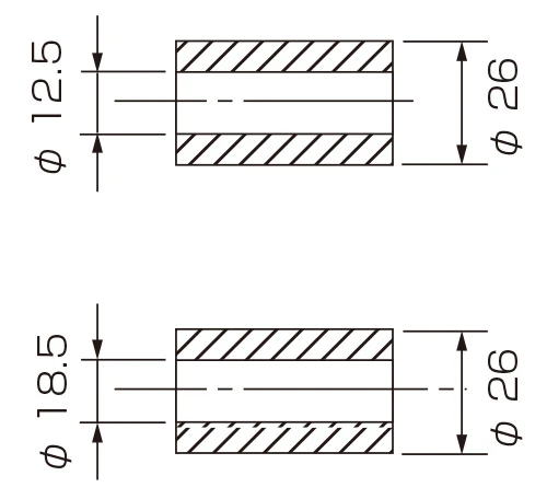
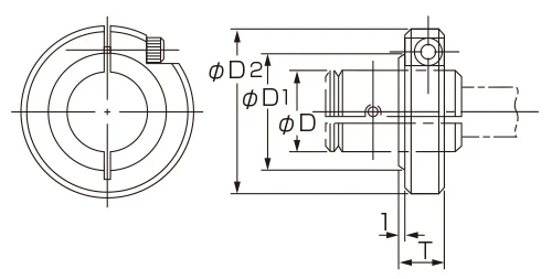
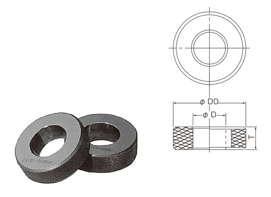
Masters for Inner Diameter Measuring Heads
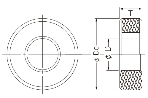
| Basic specifications | ||
| Nominal Dimension Φ D | Φ D 0 | T |
| Φ 4 ≤ Φ D ≤ Φ 5 | 30 | 10 |
| Φ 5 < Φ D ≤ Φ 8 | 12 | |
| Φ 8 < Φ D ≤ Φ 10 | 34 | 15 |
| Φ 10 < Φ D ≤ Φ 14 | ||
| Φ 14 < Φ D ≤ Φ 20 | 42 | |
| Φ 20 < Φ D ≤ Φ 26 | 50 | |
| Φ 26 < Φ D ≤ Φ 32 | 58 | 20 |
| Φ 32 < Φ D ≤ Φ 38 | 66 | |
| Φ 38 < Φ D ≤ Φ 44 | 74 | 25 |
| Φ 44 < Φ D ≤ Φ 50 | 84 | |
| Φ 50 < Φ D ≤ Φ 65 | 104 | |
| Φ 65 < Φ D ≤ Φ 80 | 124 | |
| Φ 80 < Φ D ≤ Φ 95 | 144 | 30 |
| Φ 95 < Φ D ≤ Φ 100 | 164 | |
| KB type | ||
| Nominal Dimension Φ D | Φ D 0 | T |
| Φ 1 ≤ Φ D ≤ Φ 3 | 16 | 3 |
| Φ 3 < Φ D ≤ Φ 6 | 20 | 4 |
| Φ 6 < Φ D ≤ Φ 10 | 25 | 5 |
| Φ 10 < Φ D ≤ Φ 14 | 32 | 7 |
| Φ 14 < Φ D ≤ Φ 18 | 40 | |
| Φ 18 < Φ D ≤ Φ 20 | 50 | |
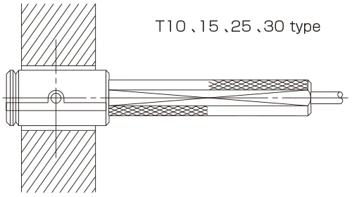
Usage Examples of Inner Diameter Measuring Heads
Select from the extension range of measuring heads to suit conditions like measurement hole depth or roughness.
| Ordinary |
T10, 15, 25, 30 type
 |
B03, 05 type
 |
| Determining Measuring Position |
T10, 15 type
 |
|
| Rough Surface |
TR09, 15 type
 |
|
| Small Diameter |
KB type
 |
K04 type
 |
| When Mounted on Stand |
Replacement bushing
 |
Horizontal stand 100H
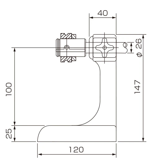 |
Hand Type Outer Diameter Measuring Heads
Hand Type Outer Diameter Measuring Heads are useful for handle type measurements.
The most commonly used type, and a model with carbide-faced V stand is also available for enhanced durability.
* Ensure that the measurement surface roughness of the measured object is less than Ra1.6.
Combination A/E Converter Deltair
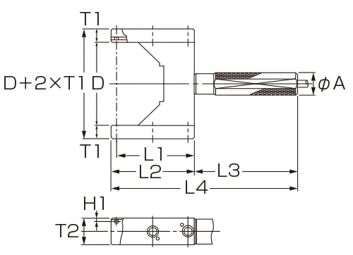
H Type
Measurements are made by simply clamping the object being measured, and it is suitable for measuring workpieces like the outer diameter of crankshaft pins.
| H Type | |||||||||
| Model | Nominal Dimension Φ D | T1 | H1 | L1 | L2 | L3 | L4 | T2 | φ A |
| H type | Φ 15 ≤ Φ D ≤ Φ 20 | 17.5 | 5 | 60 | 68 | 110 | 178 | 20 | 20 |
| Φ 20 < Φ D ≤ Φ 60 | 15 | 5 | 65 | 73 | 110 | 183 | 20 | 20 | |
| Φ 60 < Φ D ≤ Φ 80 | 15 | 5 | 70 | 78 | 110 | 188 | 22 | 22 | |
| Φ 80 < Φ D ≤ Φ 100 | 15 | 5 | 80 | 88 | 110 | 198 | 22 | 22 | |
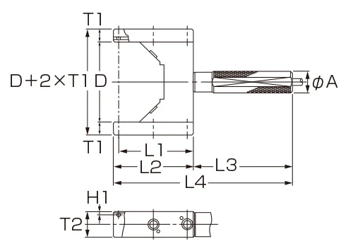
T-CH Type
Carbide-faced V stand provides even greater durability than the H Type.
| T-CH Type | |||||||||
| Model | Nominal Dimension Φ D | T1 | H1 | L1 | L2 | L3 | L4 | T2 | φ A |
| T-CH type | Φ 15 ≤ Φ D ≤ Φ 20 | 17.5 | 5 | 60 | 68 | 110 | 178 | 20 | 20 |
| Φ 20 < Φ D ≤ Φ 60 | 15 | 5 | 65 | 73 | 110 | 183 | 20 | 20 | |
| Φ 60 < Φ D ≤ Φ 80 | 15 | 5 | 70 | 78 | 110 | 188 | 22 | 22 | |
| Φ 80 < Φ D ≤ Φ 100 | 15 | 5 | 80 | 88 | 110 | 198 | 22 | 22 | |
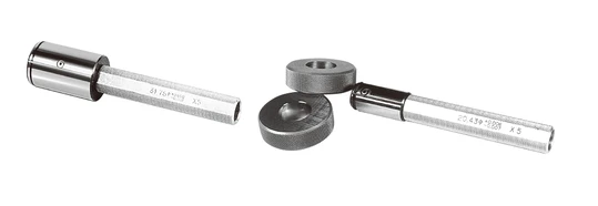
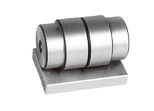
Masters for Hand Type Outer Diameter Measuring Heads
One each of large and small master for a hand-type measuring head is mounted on the master stand.
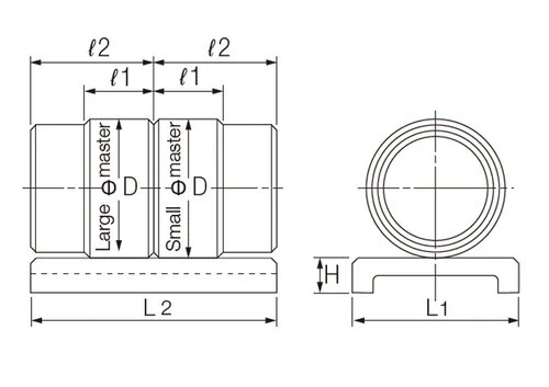
| Basic specifications | |||||
| Nominal Dimension Φ D | ℓ1 | ℓ2 | L1 | L2 | H |
| Φ 15 ≤ Φ D ≤ Φ 20 | 20 | 35 | 22 | 70 | 10 |
| Φ 20 < Φ D ≤ Φ 30 | 20 | 35 | 40 | 70 | 10 |
| Φ 30 < Φ D ≤ Φ 45 | 20 | 35 | 50 | 70 | 10 |
| Φ 45 < Φ D ≤ Φ 60 | 20 | 40 | 60 | 80 | 12 |
| Φ 60 < Φ D ≤ Φ 80 | 25 | 45 | 80 | 90 | 15 |
| Φ 80 < Φ D ≤ Φ 100 | 25 | 45 | 100 | 90 | 15 |
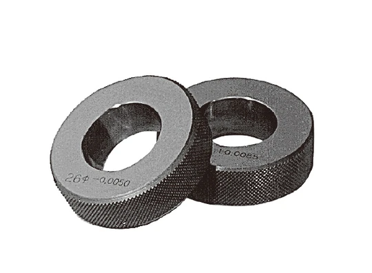
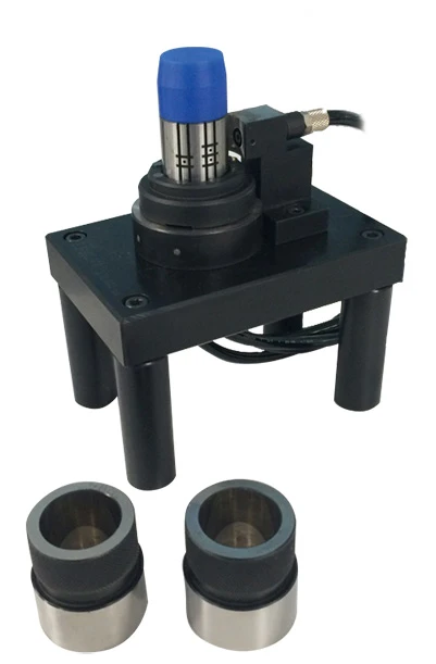
Ring Type Outer Diameter Measuring Heads
Ring type of outer diameter measuring head.
The object being measured is inserted into the ring-shaped measuring head for measurement.
Used when the object being measured is small.
* Ensure that the measurement surface roughness of the measured object is less than Ra1.6.
Configurations A/E Converter Deltair
R Type
The object being measured is simply inserted into the ring-shaped measuring head for measurement.
| R Type | ||||||||||
| Model | Nominal Dimension Φ D | T1 | L2 | φ A | ||||||
| R type | Φ 4 < Φ D ≤ Φ 10 | 5 | 20 | 52 | ||||||
| Φ 10 < Φ D ≤ Φ 20 | 5 | 20 | 62 | |||||||
| Φ 20 < Φ D ≤ Φ 30 | 5 | 20 | 72 | |||||||
| Φ 30 < Φ D ≤ Φ 40 | 5 | 20 | 82 | |||||||
| Φ 40 < Φ D ≤ Φ 50 | 5 | 20 | 92 | |||||||
RH Type
R Type with handle attached.
| RH Type | |||||||||
| Model | Nominal Dimension Φ D | T1 | H1 | L1 | L2 | L3 | L4 | T2 | φ A |
| RH type | Φ 4 < Φ D ≤ Φ 10 | 5 | 20 | 24 | 110 | 160 | 52 | 20 | 20 |
| Φ 10 < Φ D ≤ Φ 20 | 5 | 20 | 29 | 110 | 170 | 62 | 20 | 20 | |
| Φ 20 < Φ D ≤ Φ 30 | 5 | 20 | 34 | 110 | 180 | 72 | 20 | 22 | |
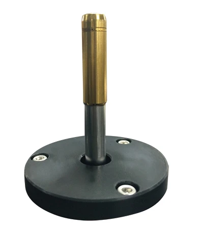
Stand Type Outer Diameter Measuring Heads
Stand type of outer diameter measuring head.
The object being measured is placed on the V stand for measurement.
Suitable for measuring objects like long, narrow shafts.
* Ensure that the measurement surface roughness of the measured object is less than Ra1.6.
Configurations A/E Converter Deltair
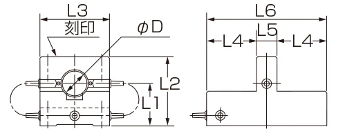
S Type
The object being measured is simply inserted by sliding it into the ring-shaped measuring head for measurement.
| S Type | |||||||
| Model | Nominal Dimension Φ D | L1 | L2 | L3 | L4 | L5 | L6 |
| S type | Φ 5 ≤ Φ D ≤ Φ 10 | 30 | 45 | 50 | 40 | 15 | 95 |
| Φ 10 < Φ D ≤ Φ 20 | 35 | 55 | 60 | 50 | 15 | 115 | |
| Φ 20 < Φ D ≤ Φ 30 | 45 | 70 | 70 | 50 | 20 | 120 | |
| Φ 30 < Φ D ≤ Φ 40 | 50 | 80 | 80 | 50 | 20 | 120 | |
| Φ 40 < Φ D ≤ Φ 50 | 55 | 90 | 90 | 50 | 20 | 120 | |
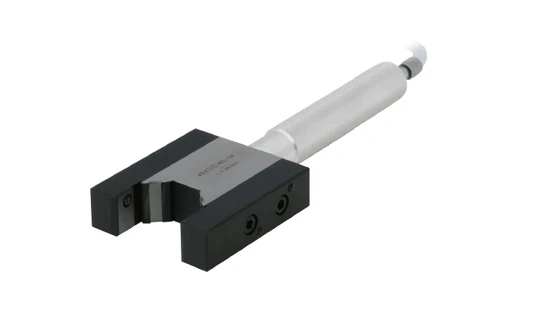
SH Type
For measurement, clamp the object being measured using a similar method to the H Type of Hand Type Outer Diameter Measuring Head.
| SH Type | ||||||||
| Model | Nominal Dimension Φ D | L1 | L2 | L3 | L4 | H1 | H2 | H3 |
| SH type | Φ 20 < Φ D ≤ Φ 35 | 5 | 20 | 50 | 100 | 70 | 78 | 93 |
| Φ 35 < Φ D ≤ Φ 45 | 5 | 20 | 50 | 100 | 70 | 78 | - | |
| Φ 45 < Φ D ≤ Φ 60 | 5 | 20 | 60 | 120 | 70 | 78 | - | |
| Φ 60 < Φ D ≤ Φ 70 | 5 | 22 | 60 | 120 | 80 | 88 | - | |
T-C SH Type
Carbide-faced V stand provides even greater durability than the SH Type.
| T-C SH Type | ||||||||
| Model | Nominal Dimension Φ D | L1 | L2 | L3 | L4 | H1 | H2 | H3 |
| T-C SH type | Φ 20 < Φ D ≤ Φ 35 | 5 | 20 | 50 | 100 | 70 | 78 | 93 |
| Φ 35 < Φ D ≤ Φ 45 | 5 | 20 | 50 | 100 | 70 | 78 | - | |
| Φ 45 < Φ D ≤ Φ 60 | 5 | 22 | 60 | 120 | 70 | 78 | - | |
| Φ 60 < Φ D ≤ Φ 70 | 5 | 22 | 60 | 120 | 80 | 88 | - | |
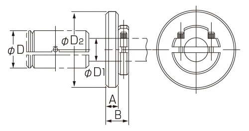
Masters for Ring Type/Stand Type Outer Diameter Measuring Heads
Masters for Ring Type/Stand Type Measuring Heads comprise a set of one large master and one small master.
The large and small masters are used interchangeably to adjust magnification.
| Basic specifications | ||||
| Nominal Dimension Φ D | Φ d | ℓ1 | ℓ2 | ℓ3 |
| Φ 4 ≤ Φ D ≤ Φ 6 | D-1 | 25 | 25 | 50 |
| Φ 6 < Φ D ≤ Φ 10 | 5 | |||
| Φ 10 < Φ D ≤ Φ 15 | 8 | |||
| Φ 15 < Φ D ≤ Φ 20 | 12 | |||
| Φ 20 < Φ D ≤ Φ 32 | 18 | 30 | 15 | 45 |
| Φ 32 < Φ D ≤ Φ 45 | 28 | |||
| Φ 45 < Φ D ≤ Φ 50 | 40 | |||
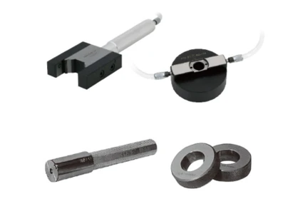
Handle Unit
Available with a long handle that can be used if the standard handle cannot reach the measurement position when measuring deep holes.
Standard Ring Stopper
Ring stoppers are used to keep the measurement depth fixed. Used for clamping the measuring head or handle.
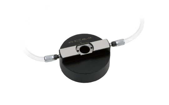
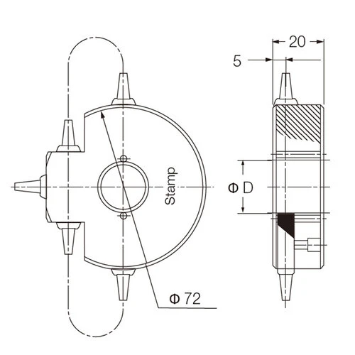
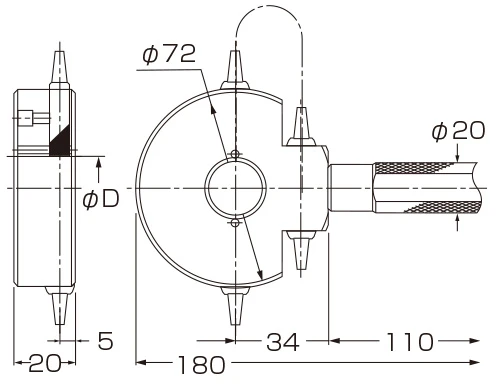
High-precision JET
Highly accurate JET is an interval and outer diameter measurement JET that improves the repeat accuracy by replacing a conventional one diameter measurement nozzle, and adopting the multiway measurement nozzle.
Used in combination with an A/E converter.
Supports supply pressure of 0.25 MPa.
A stand is also available to suit the intended use.
<Typical Configuration>
| Basic specifications | ||||||||
| Product code | Nominal Dimension Φ D | A Type | B Type | C Type | ||||
| Inner Diameter | Outer Diameter | Measuring range | Repeatability | Measuring range | Repeatability | Measuring range | Repeatability | |
| 4300613 | - | Φ 1.5 ≤ Φ D < Φ 2.5 | 5 μm | 0.2 μm | - | - | - | - |
| 4300614 | 4300617 | Φ 2.5 ≤ Φ D < Φ 4 | 10 μm | 0.2 μm | - | - | - | - |
| 4300615 | 4300618 | Φ 4 ≤ Φ D < Φ 7 | 10 μm | 0.1 μm | 15 μm | 0.15 μm | 20 μm | 0.2 μm |
| 4300616 | 4300619 | Φ 7 ≤ Φ D < Φ 14 | 10 μm | 0.1 μm | 15 μm | 0.15 μm | 20 μm | 0.2 μm |
Note: Contact your sales representative if you require diameters over Φ14, installing multiple units or have questions about the installation method.
Note: Φ D = Measured diameter
High-precision JET Master
The high-precision JET masters are used in two-master sets, one upper limit and one for lower limit.
Upper limit and lower limit masters are changed to adjust magnification.
A middle limit master is also available when required.
| Basic specifications | |||
| Product code | Nominal Dimension Φ D | Φ D0 | T |
| 4300620 | Φ 1.5 ≤ Φ D ≤ Φ 3 | 16 | 3 |
| Φ 3 < Φ D ≤ Φ 4 | 20 | 4 | |
| 4300621 | Φ 4 < Φ D ≤ Φ 5 | 30 | 10 |
| 4300622 | Φ 5 < Φ D ≤ Φ 8 | 30 | 12 |
| Φ 8 < Φ D ≤ Φ 14 | 34 | 15 | |
| Basic specifications | |||||
| Product code | Nominal Dimension Φ D | φ d | ℓ1 | ℓ2 | ℓ3 |
| 4300623 | Φ 2.5 ≤ Φ D ≤ Φ 6 | 5 | 25 | 25 | 50 |
| 4300624 | Φ 6 < Φ D ≤ Φ 10 | 5 | 25 | 25 | 50 |
| 4300625 | Φ 10 < Φ D ≤ Φ 14 | 8 | 25 | 25 | 50 |
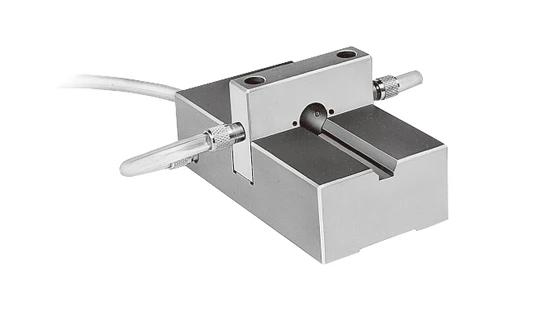
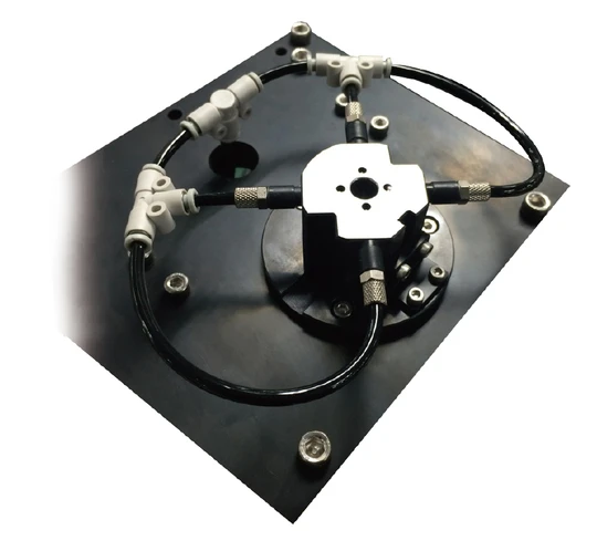
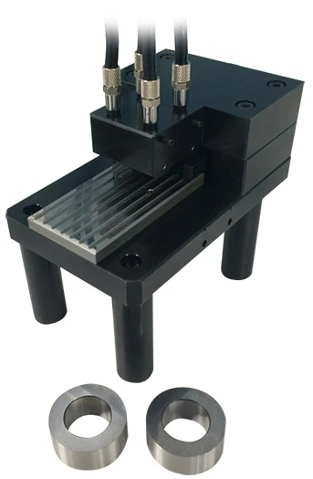
Multipoint Simultaneous Measuring Heads
Multiple measurement items can be made at the same time with a single instrument.
Heads can be tailored to suit the customer's specific requirements.
Example of Measuring Heads
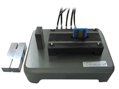
| 4-heads for piston diameter, squareness and coaxiality measurements | ||
 |
Measuring items | |
 |
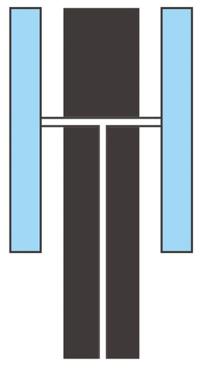
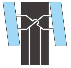
Inner diameter measurement (2 cross-sections) | |
| Top/bottom mounted nozzles measure the inner diameter in 2 cross-sections by simply inserting the workpiece. | ||
 |
Squareness measurement | |
| Squareness is measured with stepped nozzles. (workpiece rotated 180°) | ||
 |
Coaxiality measurement | |
| Coaxiality is measured by measuring the wall thickness. (workpiece rotated one revolution) | ||
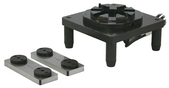
| 4-heads for piston thickness measurements | ||
 |
4-heads for piston thickness measurements | |
 |
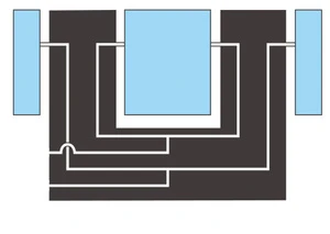
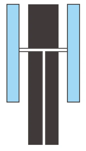
Thickness measurement (4 locations) | |
| Top/bottom mounted nozzles measure the thickness of the workpiece. Thickness is measured in 4 locations by simply placing the workpiece of the stand. |
||
| 5-heads for cylinder groove width measurements | ||
 |
Measuring items | |
 |
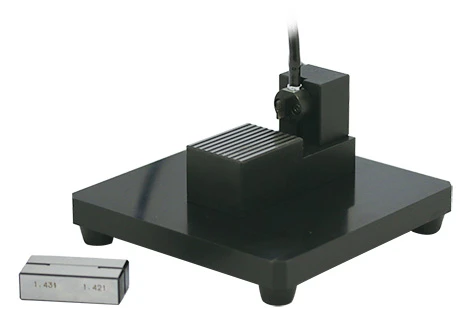
Width measurement (5 locations) | |
| Nozzles mounted at each end of the head plate measure the width of the workpiece. Width is measured in 5 locations by simply placing the workpiece of the head plate. | ||
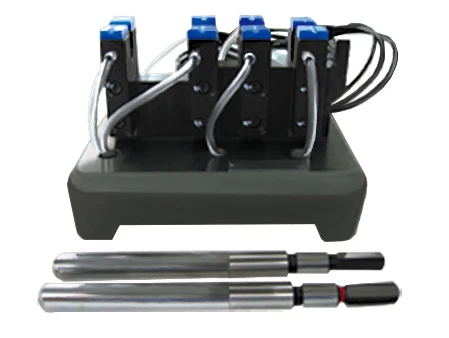
| 4-heads for shaft outer diameter measurements | ||
 |
Measuring items | |
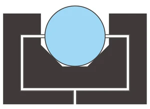 |
Outer diameter measurement (4 locations) | |
| Nozzles mounted on both sides measure the outer diameter thickness of the workpiece. Outer diameter is measured in 4 locations by simply placing the workpiece of the head V stand. | ||
| Cylinder center distance measurement | ||
 |
Measuring items | |
 |
Center distance measurement | |
| Measures the center distances of the workpiece. Measurements are made by simply inserting the workpiece. |
||
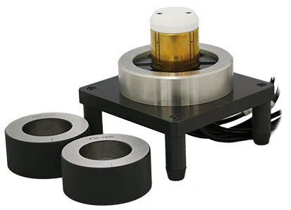
| Cylinder inner diameter, squareness, and cylindricity measurement | ||
 |
Measuring items | |
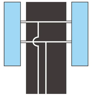 |
Inner diameter (2 cross-sections), cylindricity measurements | |
| Top/bottom mounted nozzles measure 2 cross-sections of the inner diameter and cylindricity by simply inserting the workpiece. | ||
 |
Squareness measurement | |
| Squareness is measured with stepped nozzles. Nozzles are mounted in 2 locations, so measurement is made by simply inserting the workpiece without having to rotate it. |
||
| Rotor groove width measurement | ||
 |
Measuring items | |
 |
Width measurement | |
| Nozzles mounted at each end of the head plate measure the width of the workpiece. Width is measured by simply placing the workpiece of the head plate. | ||
| Bearing flatness measurement | ||
 |
Measuring items | |
 |
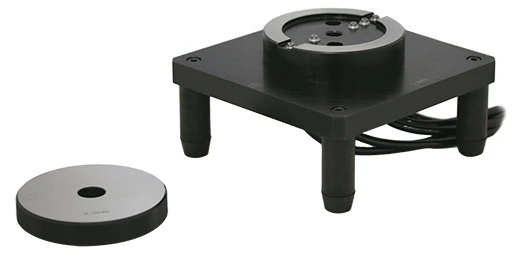
Flatness measurement | |
| Five nozzles measure the flatness of the workpiece. Measurements are made by simply placing the workpiece. |
||
Related Products