Features
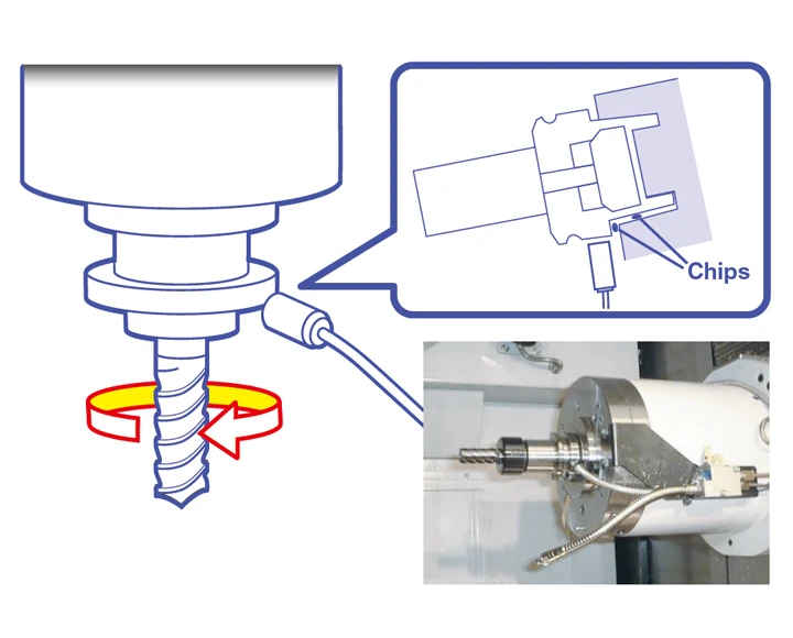
What are the sudden machining defects by chips in the tool chuck?
machining center, defects can be generated during ATC when chips get into the space between the tool taper and the main spindle. For years, machining centers have looked for a solution to this problem, which is particularly prevalent during high-speed cutting of aluminum.
Sensor head automatic tuning function
Replacing only the sensor is possible if damage occurs in the sensor for any reason. After replacing it,combination adjustment of controller and sensor head is completed by removing the tool holder from the spindle and clicking"sensor adjustment"button.
Monitoring high-speed cutting of aluminum
Because of shorter processing times, reductions in the amounts of coolants, and other aluminum process demands, the frequency of chips getting into the tool taper during ATC is increasing. During high-speed cutting of aluminum in particular, a measurement instrument must be able to detect 100% of chip invasion into the tool taper, so defects are not generated.
0.3 second measuring time
An eddy-current sensor allows measurement in a mere 0.3 seconds (at 600 rpm).
Since the measuring tool is selectable, measuring time is not affected by the cycle time. A dedicated run-out detection system algorithm (patent pending) calculates true run-out for detection capability that cannot be achieved by commercially available eddy sensors. All of this means that the system delivers precise, reliable detection in an automated line.
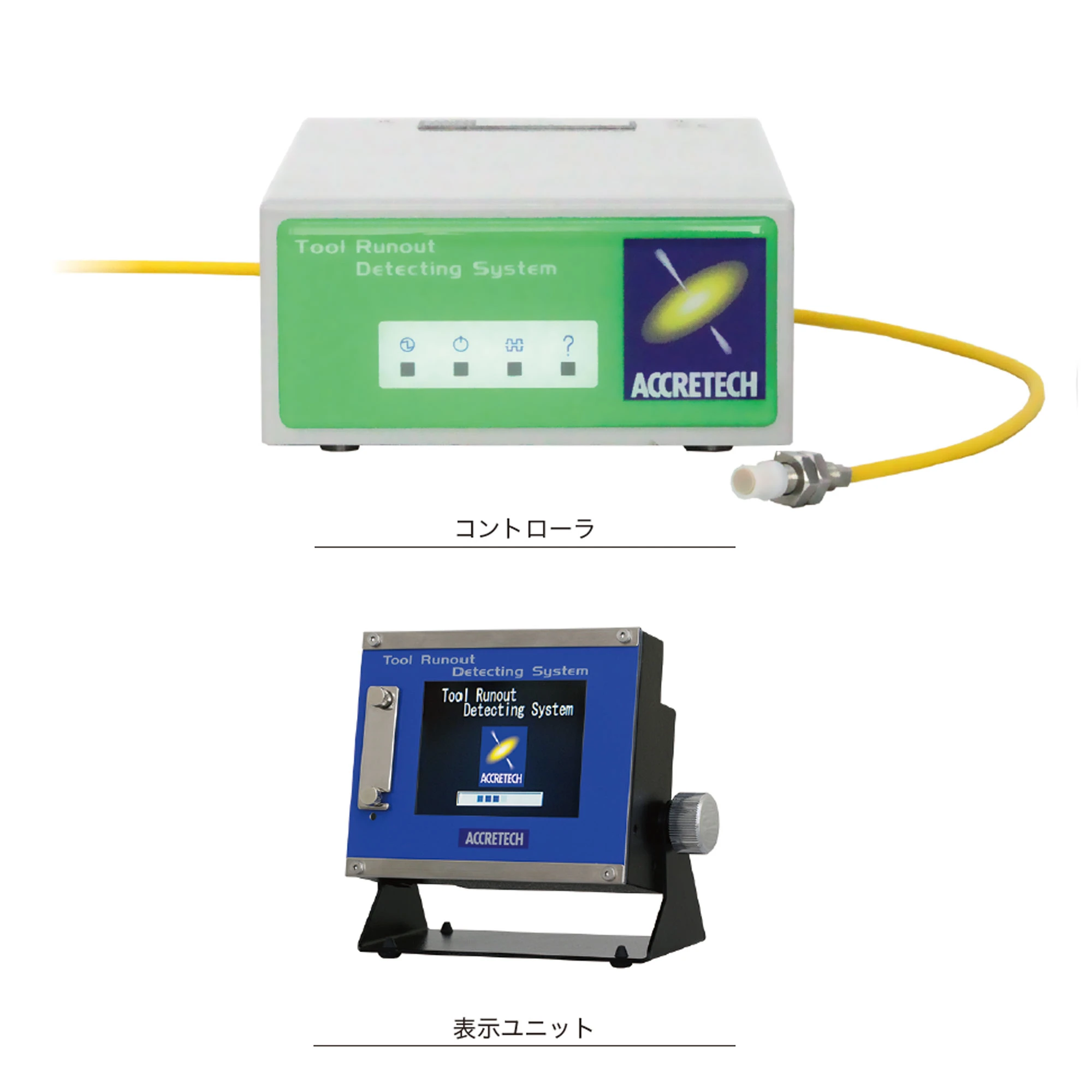
External view
Controller
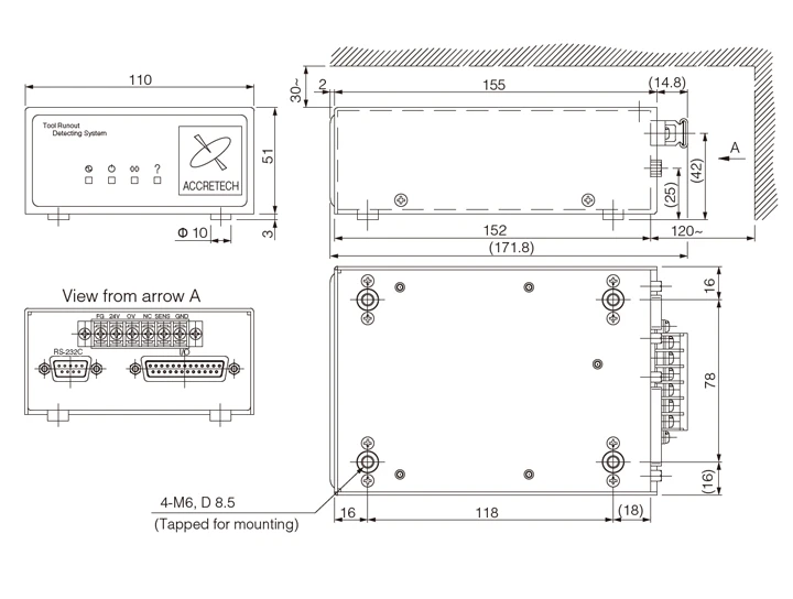
<Installation precautions>
1. Allow at least 30 mm of space above the device.
2. Allow at least 120 mm of space behind the device.
3. Limit the screw-in depth of the mounting screws(M6)to 8 mm.
4. Install the device at a location where it will not be splashed with coolant or other liquids.
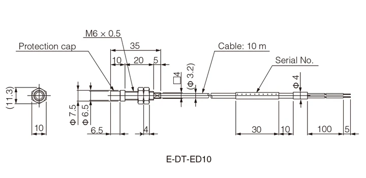
Sensor head
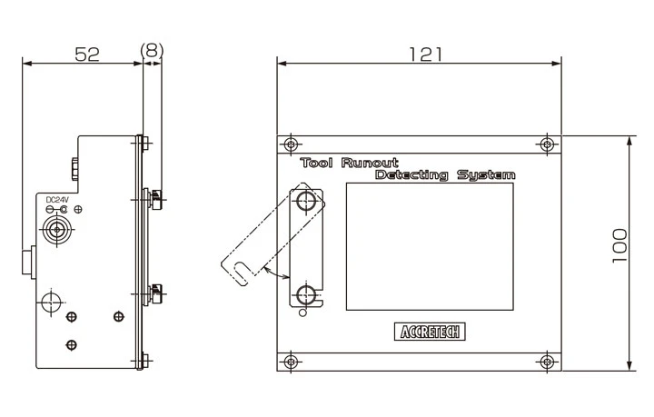
Display unit
<Precautions for sensor head mounting>
1. Do not extend or cut the sensor head cable. Prepare a cable in an appropriate length by confirming the cable layout.
Use a two-way device when cutting the cable for connecting the terminal.
2. Although the sensor head is tested in accordance with waterproofing structure (Protective class IP 67) and anti-coolant characteristic test, it does not mean that it is guaranteed for all type of coolant.
3.Replaceable “Protective cap” is equipped in the sensor head for abrasion protection against chips. Do not remove this “Protective cap” when the system is operating.
4.Use protective pipe for sensor head cables to protect from chips. Maintain the cable bending more than R>35 mm (1.4” approx).
5. Do not use the sensor head cable as it is wound.
Specifications
| Basic specifications | |
| Product name | ATC Run-Out Detection System |
| Model number(representative) | Controller: AT50361 Φ 5 sensor head: E-DT-ED10 |
| Applications | Tool holder flange runout detection |
| Acceptable tools | BT30, BT40, BT50, HSK63A, etc. |
| Sensor head installation range | 1.0 ±0.1 mm from tool holder flange surface |
| Measuring range | ±0.2 mm |
| Tool registration | 32 max |
| Resolution | 0.5 μm |
| Repeatability | ≤ 3 μm/4 σ*Using our master tool holder (BT40) |
| Tool rotation speed | 120, 600, 1200 rpm |
| Cycle time | Up to 0.3 sec (at 600 rpm, with default settings) |
| Display unit | ㎛、mm |
| IP code | IP67 (sensor head) * Do not expose controller to water , oil, or other liquids. |
| Ambient usage temperature / Temperature | 0 to 40℃ |
| Vibration resistance | 3.66 G max. (x, y, z-axis directions) *JIS C 60068-2-6compliance *Sweep 25 min at 10 to 55 Hz (5 min per sweep) |
| Shock resistance | Sensor head: 50 G max (r, y, z-axis directions,10 times) Controller: 20 G max (x, y, z-axis directions, 10 times) |
| CE mark | Compliance |
| Outer dimensions (W) x (D) x (H) / Weight | 110 × 171.8 × 54 mm/0.6 kg |
| Power source / power consumption | DC24 V ±10% / 14 W |
Options
| Standard system | ||
| Product code | Product name | Remarks |
| 991013 | Controller | AT50361 |
| 991014 | Φ 5 sensor head 10 m | E-DT-ED10 |
| 4216683 | Protective housing for controller | AM50316-D002 |
| 4219670 | RS-232C cable 5 m | D-Sub 9-pin cross-wiring |
| 4220793 | RS-232C cable 10 m | D-Sub 9-pin cross-wiring |
| 4206865 | IO cable length 15 m | AT50304 |
| 4206864 | IO cable length 10 m | AT50302 |
| 4206868 | Power cable 15 m | AT50305 |
| 4206867 | Power cable 10 m | AT50303 |
| 4220361 | Casing tube 9.8 m | For sensor head cable protection |
| 4206874 | Operation manual, Instruction manual, Japanese (2 copies each) | ー |
| 4206875 | Operation manual, Instruction manual, English (2 copies each) | ー |
| 4206900 | Operation manual, Instruction manual, Chinese (2 copies each) | ー |
| 4206899 | Windows application CD | AS50345 |
| 4210677 | Protection cap (x1) | AM22203-D904 For sensor head protection |
| Display unit | ||
| Product code | Product name | Remarks |
| 4220521 | Display unit | AT50366 Display language: Japanese/English |
| 4220632 | Display unit | AT50366K Display language: Korean/English |
| 4220633 | Display unit | AT50366C Display language: Chinese/English |
| 935410 | Stand for display unit | ー |
| 935411 | AC adapter for Japan | Input AC 100 V to 240 V, Plug A type |
| 935460 | AC adapter for North America | Input AC 100 V to 240 V, Plug A type |
| 935461 | AC adapter for Europe | Input AC 100 V to 240 V, Plug C type |
| 935462 | AC adapter for Korea | Input AC 100 V to 240 V, Plug C type |
| 935463 | AC adapter for China | Input AC 100 V to 240 V, Plug A type |
| 4206867 | Power cable 10 m | AT50303 |
| 4206868 | Power cable 10 m | AT50305 |
| 4220522 | Operation manual Japanese | ー |
| 4220523 | Operation manual English | ー |
| 4220634 | Operation manual Chinese | ー |
| 4220610 | Operation manual Korean | ー |
| 4220574 | USB memory 4 GB | HUB-PF04GTA-BK-TSE |
Related Products